SITCOMTN-043
Auxiliary Telescope Polycold chiller maintenance procedures.#
Abstract#
The Polycold chiller in the AuxTel dome needs to be recharged periodically (approximately once a year) to keep the coolant pressures high enough. This technote describes the procedure.
In addition, both the internal absorber in the chiller compressor and the external absorber need to be changed out approximately once per year. This technote also documents those procedures.
Introduction#
The AuxTel CCD needs to operate at approximately -100C in order to function properly. To keep the CCD cold, the system employs a Polycold Compact Cooler (PCC). The compressor is located on the first floor of the AuxTel dome, next to the CCD electronics cabinet. The coolant fluid, called PT-30, is a proprietary mixture of hydrocarbons, believed to consist of propane, ethane, and methane. The compressor pumps high pressure gas up to the second floor of the dome and into the red Dewar chamber which contains the CCD. Inside the Dewar chamber is the cold head, which allows the high pressure fluid to expand through a small opening, cooling the cold head. The coolant liines that carry the collant to and from the CCD Dewar are jacketed with a stainless steel braid. It’s important to remember that since the lines are about 30 meters long, most of the coolant is in the lines, not in the compressor. So when you are re-charging the system, you are really re-filling the lines.
The most important aspect when working with this system is to avoid contamination. If contaminants (meaning air and anything but pure PT-30) get into the system, they can cause a clog to occur at the cryohead where the gas changes from liquid to gas and therefore reduces and essentially stops cooling the instrument. Cleaning the cryohead is basically impossible and not worth the effort. Although a new one can be purchased for ~5K$, changing the head is a large endeavour as the instrument needs to be removed from the telescope and disassembled in a clean room, which is always a risky procedure. With this system, prevention is the best medicine.
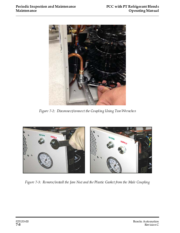
The system uses Aeroquip fittings which hold pressure when disconnected. These fitting prevent gas from escaping or air from entering into the coolant lines. When removing or attaching these fittings, two wrenches are required. these wrenches are in the electronics cabinet on the first floor. The smaller wrench is used to hold the part of the fitting which does not turn, while the larger wrench tightens or loosens the fitting. This is shown in Figure 1:
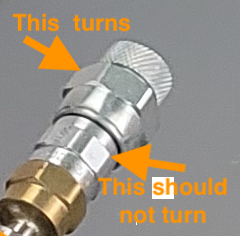
Figure 1: Aeroquip fittings, which prevent gas from escaping or air from entering.
How to know when the system needs re-charging#
The pressure on the high-pressure (supply) and low-pressure (return) are monitored by the pressure gauges which are attached to the compressor and read by the electronics sitting on top of the compressor. These pressures are available in the EFD. They can be read in the “AuxTel (LATISS) Temperatures and Pressures” dashboard, or in the EFD at the “lsst.sal.ESS.pressure” variable. pressure0 is the high side pressure and pressure1 is the low side. These pressures are in Pascal. In normal operation, the high pressure side should be at 275-350 PSI (1900-2400 kPA). Over time, there is a small amount of leakage and the pressure drops. In 2022, as these pressures dropped, we started to see excursions where the temperature of the cold head would rise abruptly, especially when the exterior temperatures went down. When the cold head lost cooling capacity, both the high and low side pressured would drop further. Figures 2 and 3 show these excursions and how a re-charge of the coolant as described in this technote fixed the issue.
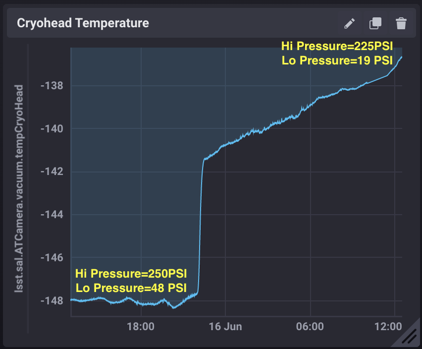
Figure 2: Temperature rise event showing sudden rise in cold head temperature and associated loss of pressure.
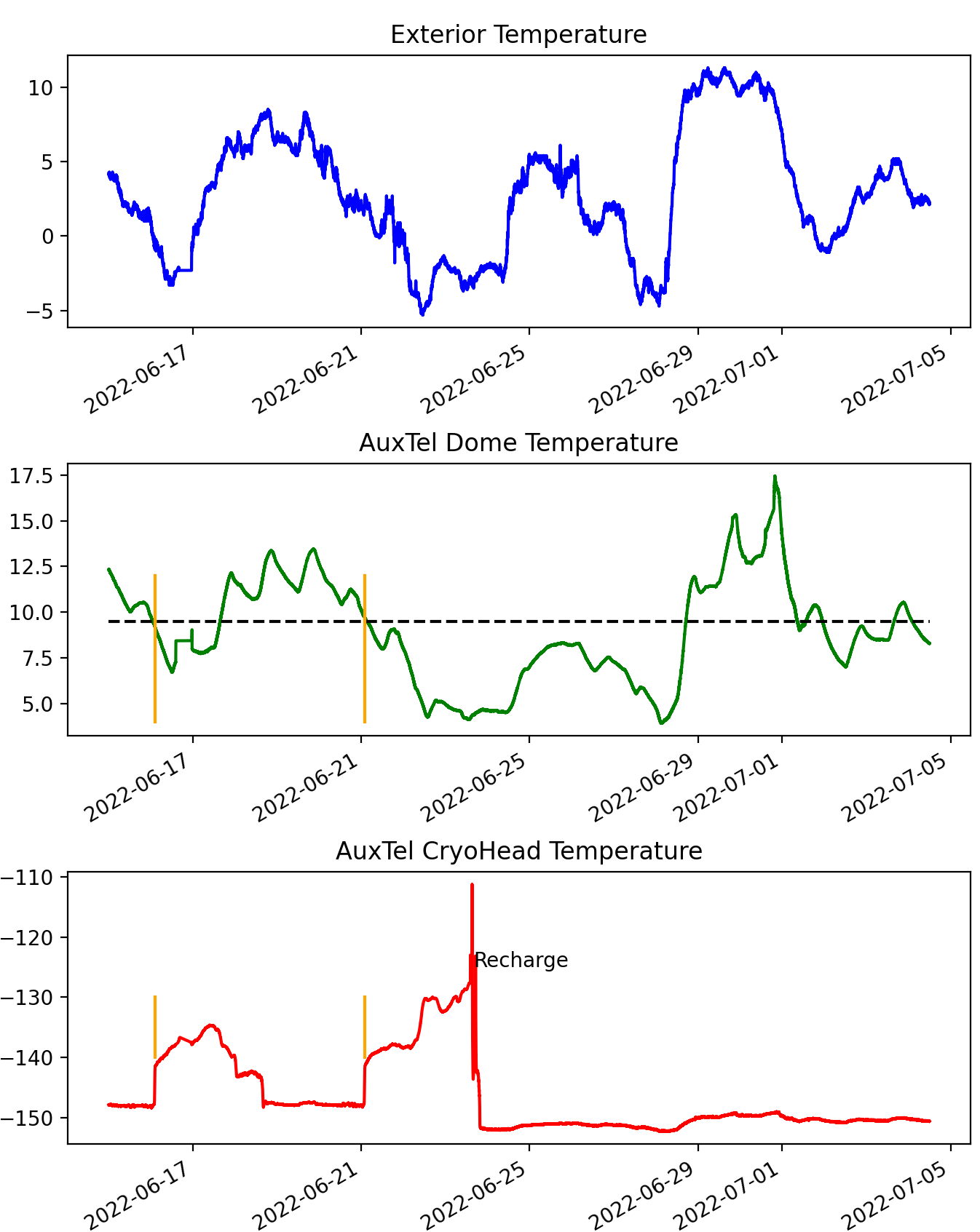
Figure3: Correlation of temperature rise events with external temperature and how re-charging fixed the problem.
Recharge Procedure#
Evacuating the recharge system must be done prior to refilling. There are many couplings so caution must be taken to make sure there are no leaks before connecting to the polycold compressor. It is recommended to pump in stages to make sure no components are leaking. The procedure is described below, followed by pictures of each stage.
Connect the 3/8 hose to the pump with the vacuum gage on a T- at the end with a valve after the hose. The T has a Schrader valve which works well.
With valve closed, run pump for ~10-20 minutes. You should be able to pump to ~30 mTorr.
Note that the valves get air pockets in them and will need to be actuated a few times once pumping as the vacuum increases.
Also, the gauge has a knack for unseating. It also leaks a touch. It might need to be removed and reseated if adequate vacuum is not being achieved.
Attach tank fixture to the tank using a small amount of Teflon tape on the interface between the fixture and the tape. The Teflon tape is (unfortunately) required to get a good seal due to scuffs on the head due to a damaged surface on tank we connected it to in Tucson.
If the fixture is already attached, be sure to vent the entire fixture
This is best done by attaching a AeroQuip fitting from the pump line (but disconnected from the pump) to one side, also be sure to open the needle valve on the tank fixture to ensure the entire fixture gets vented.
Open the needle valve on the tank fixture (until it stops, then turn back and close it by ~1/4 turn). Connect pump, then open the ball valve by the gauge and pump down to ~60 mTorr or better. This will take several minutes.
Close the needle valve on the tank fixture, then close the ball valve near the gauge, open the tank valve and the tank fixture will become pressurized.
Disconnect the pump from the tank fixture via the Aeroquip Fitting.
Pump out the line that will go between the tank fitting and compressor fitting.
This requires the change out of the Aeroquip+quick connect fitting adapter.
The valve on the line will need to be actuated during pump down to remove air pockets.
Pump the line to at least 70 mTorr, this will take ~5-10 minutes. Capping the line is a good idea as the AeroQuip fittings don’t handle vacuum very well and can be leaky.
Remove the cap, make sure the vacuum holds. Close the valve to the gauge and pump, then connect the line to the tank fixture. This will pressurize the line. Close the needle valve.
Remove the line from the pump fixture using the AeroQuip fitting and cap the pressurized line.
Connect vacuum line to any port of compressor fixture EXCEPT where the line from the tank fixture connects. Open the needle valve.
You should be able to pump this fixture to a better vacuum. Less than 30 mTorr.
Close the valve to the pump, connect the line from the tank fixture. This will pressurize the compressor fixture. Then remove the Aeroquip fitting to disconnect the pump. Close the needle valve.
Close the valve at the gas bottle.
Turn off the compressor.
Connect the compressor fixture to the compressor. Note the supply connected to supply etc. This should be done quickly, essentially tightening both connectors simultaneously, a few turns at a time each.
Turn the compressor back on. Let it operate for a few minutes to achieve equilibrium pressure.
Open the valve at the gas bottle while watching the line pressures. When the high side pressure has reached 275-300 PSI (1900-2070 kPa), close the valve at the gas bottle. Note that it is very important that either the valve at the gas bottle or the valve connecting the tank fixture to the compressor fixture (yellow line in Figure 8) are closed when you turn on the compressor. The recharge process happens very fast, and if these are not closed, you can easily overcharge the system.
Turn off the compressor.
Disconnect the compressor fixture from the compressor, attaching the supply and return lines as they were originally.
Turn the compressor back on. The pressures should eventually achieve 275-350PSI (1900-2410 kPa) on the high side and 50-75 PSI (345-520 kPa) on the low side and the system should be cooling well, with the cold head cooling to about -140C to -150C (123K-133K).
With the gas bottle valve closed, pump out both the tank fixture and the compressor fixture to remove coolant gas from these fixtures. Then remove the tank fixture from the gas bottle and store the pump and fixture in the AuxTel storage container until they are needed next.
Pictures of these procedures follow:
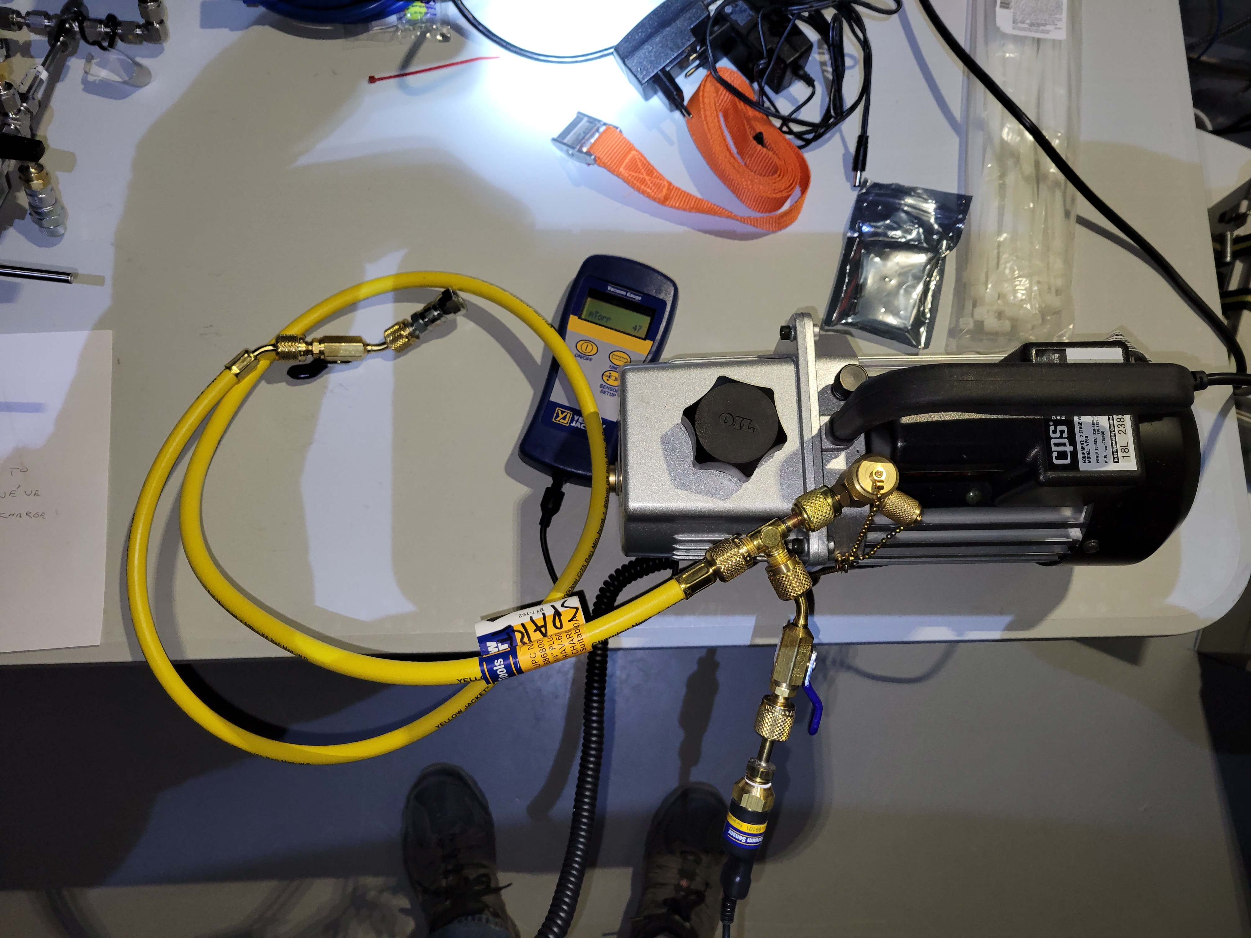
Figure 4: Pumping the pump only. The pump takes 10-20 minutes to warm up before it pumps below ~3000 mTorr. There is an oil level gauge on the side of the pump. Make sure it has adequate pump oil.
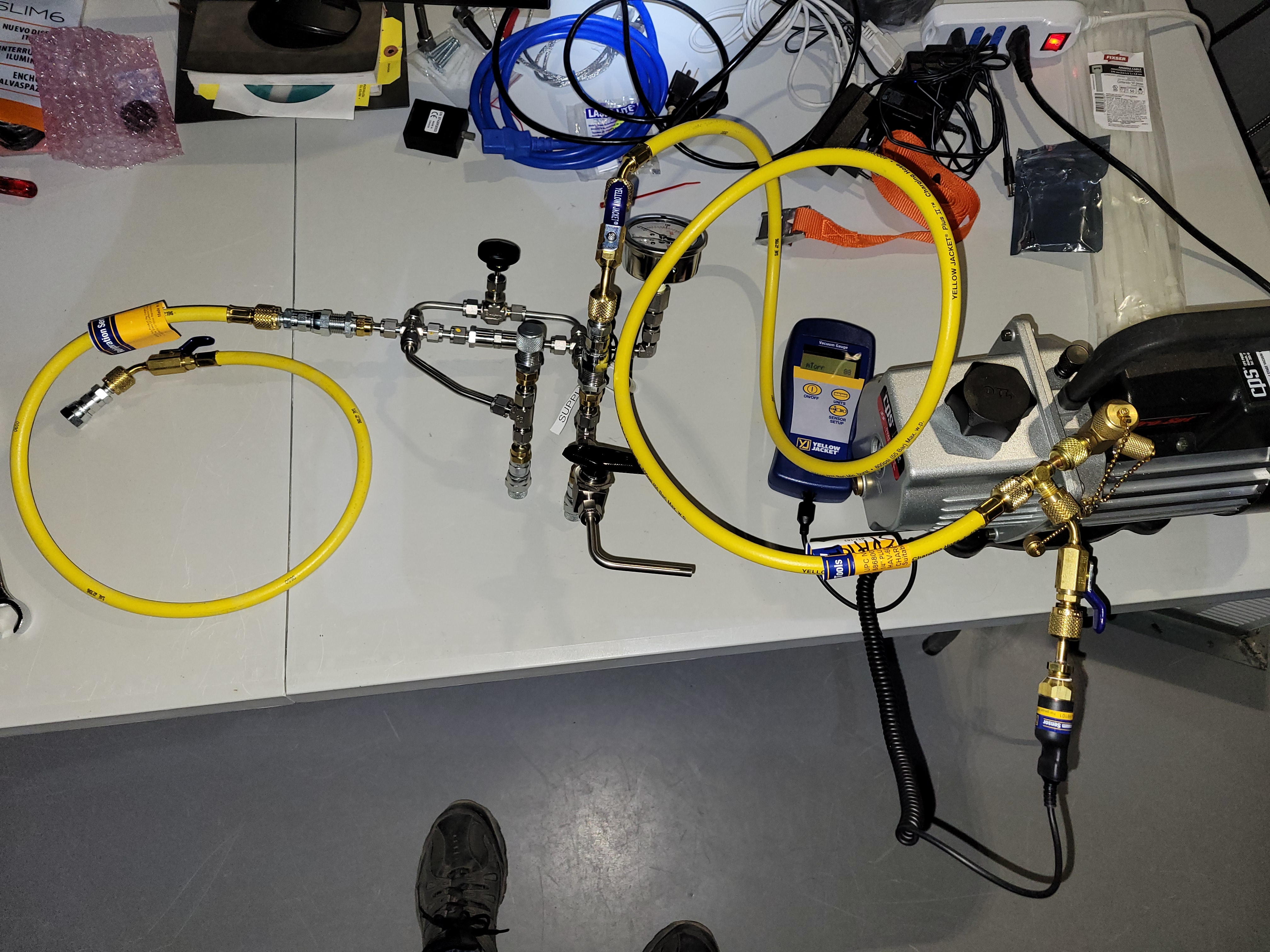
Figure 5: Pumping compressor fixture. Make sure the needle valve is open to allow evacuating the entire fixture.
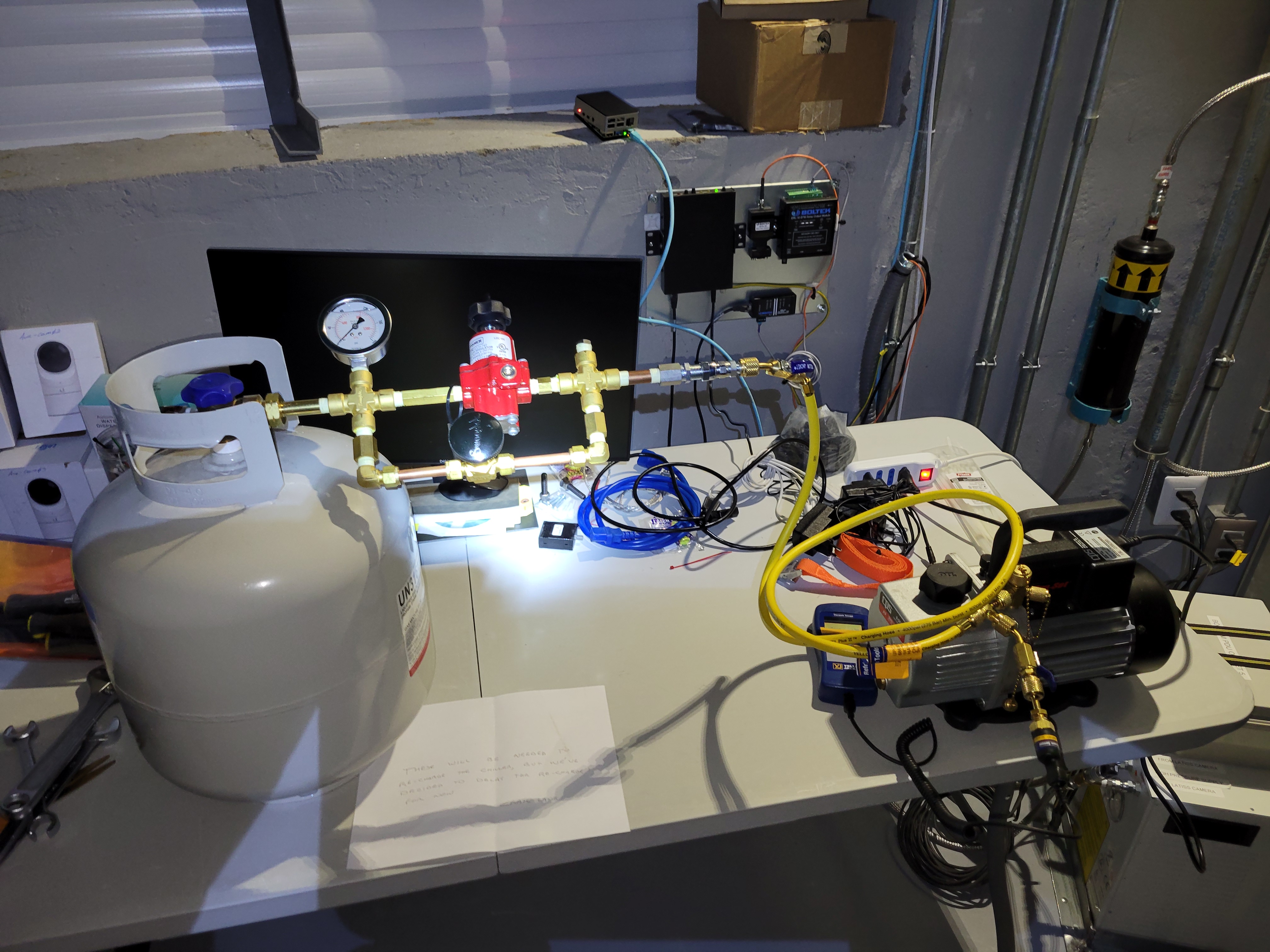
Figure 6: Pumping tank fixture. Make sure the needle valve is open to allow evacuating the entire fixture.
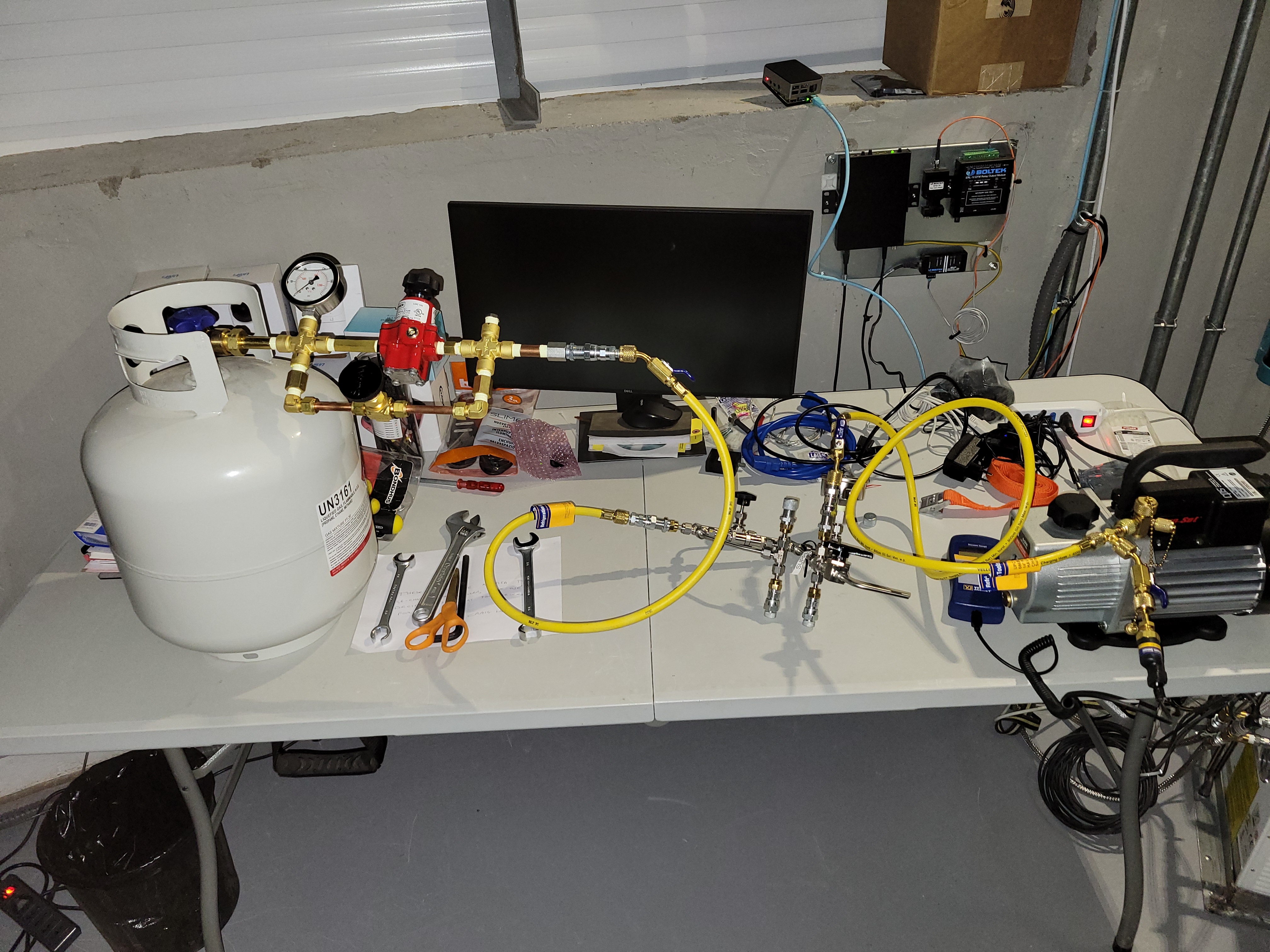
Figure 7: Pumping the combined fixture.
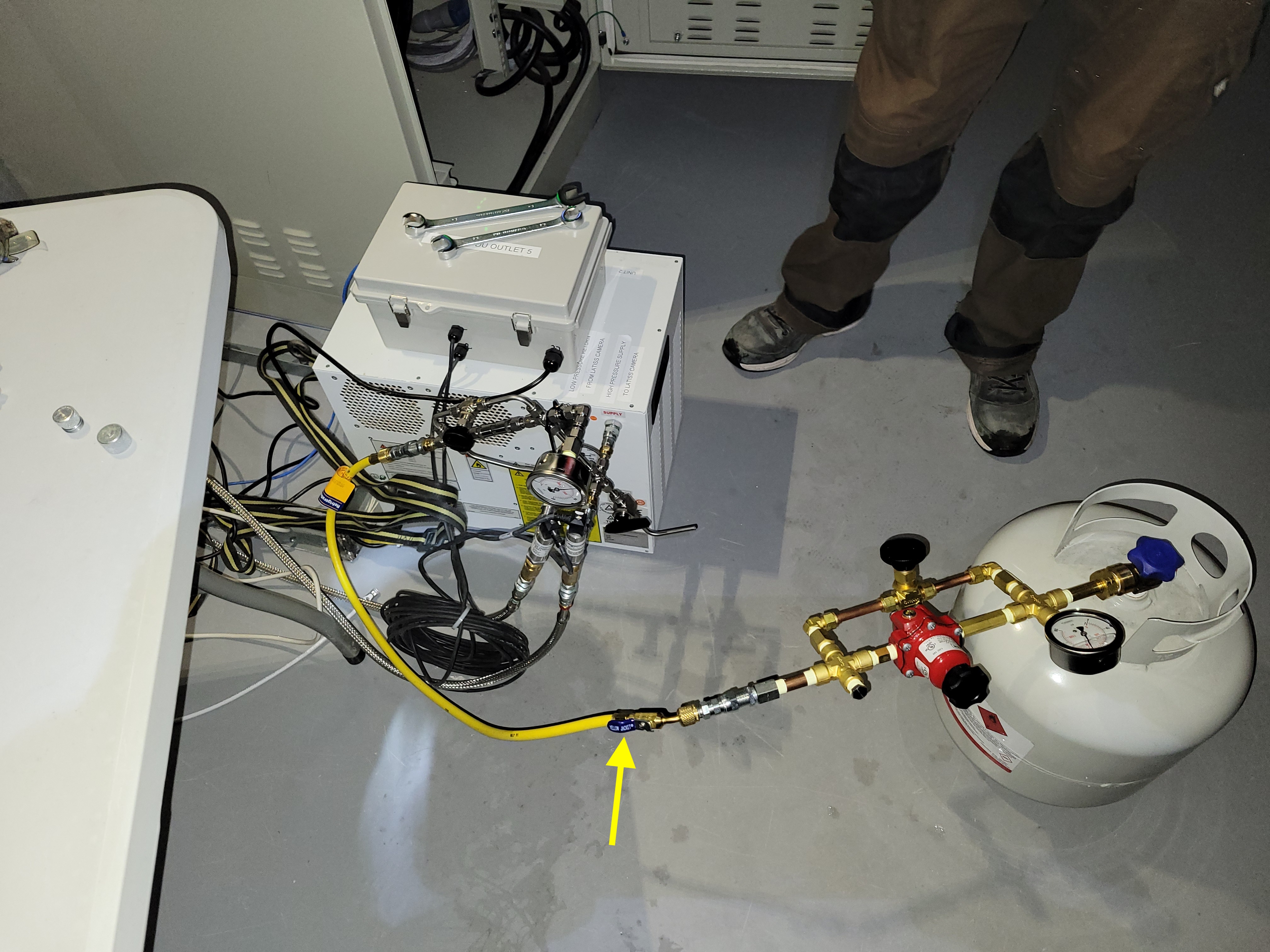
Figure 8: After completing the pumping and charging the fixtures with coolant, this shows the entire system connected to the compressor for charging.
Notes on line icing and system overcharging#
When the system was recharged in June, 2022, during the southern winter, the system was slightly overcharged. After the recharge procedure, the system high side pressure was about 305 PSI, slightly above the 300 PSI maximum stated in the manual. However, as the weather warmed and we moved into the southern summer, the pressures in the system rose steadily, and by January, 2023 the high side pressure had reached 360 PSI, well above the 300 PSI limit. Also as the weather warmed, we started to see significant icing on the chiller return line near the Dewar. See FIgure 9.
To alleviate this, the compressor was stopped for a short period, the return line was disconnected from the Dewar, the return line was de-iced, an unbroken length of insulation was slid onto the return line, the return line was re-attached, and the compressor was re-started. As seen in Figure 10, this was done without the CCD warming significantly.
After this was done, There was no longer icing near the Dewar, but significant icing was seen at the end of the insulation, in the cable wrap, as seen in Figure 11 and 12. Since we had not seen this heavy icing in the past, the hypothesis was that the icing was due to the high pressures that resulted from the overcharging, leading to basically too much cooling capacity. So in January, 2023, gas was bled out from the system in two steps to reduce the maximum pressure. This was accomplished by connecting the compressor fixture to the compressor and slowly opening the valve (with the compressor off) to bleed out gas. It is important that the vent windows are open and the vent fan is on during this procedure to prevent the flammable coolant gas from building up to potentially explosive levels. Figure 13 shows the reduction in pressure that resulted from this process, bringing the max high side pressure down to 315 PSI. After doing this, light frost was still seen occasionally on the return line in the cable wrap, but not the heavy icing that was seen earlier. However, this needs to be monitored in the future.
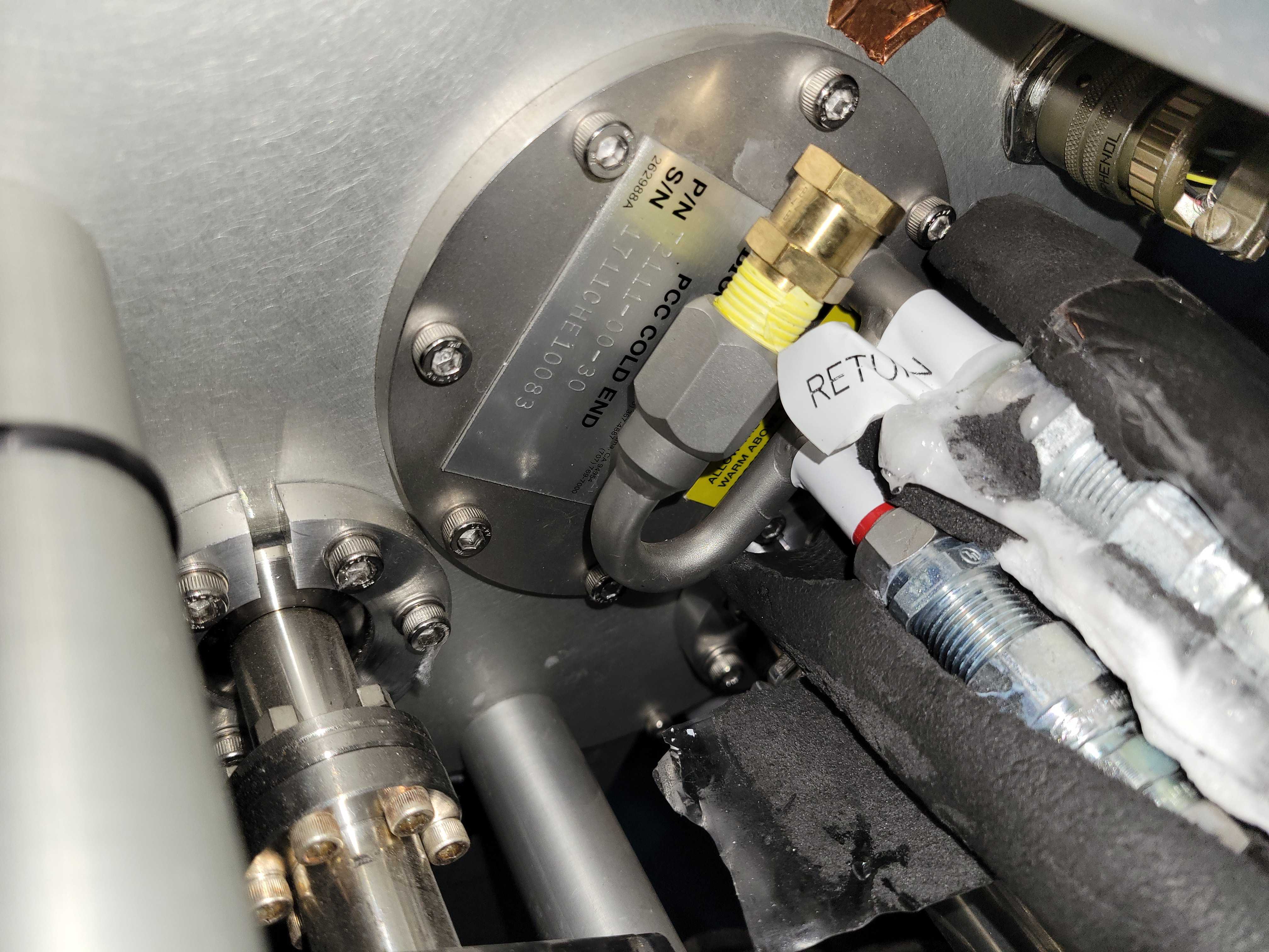
Figure 9: After removing the split insulation from the chiller lines, ice build up that could potentially force the lines apart was seen.
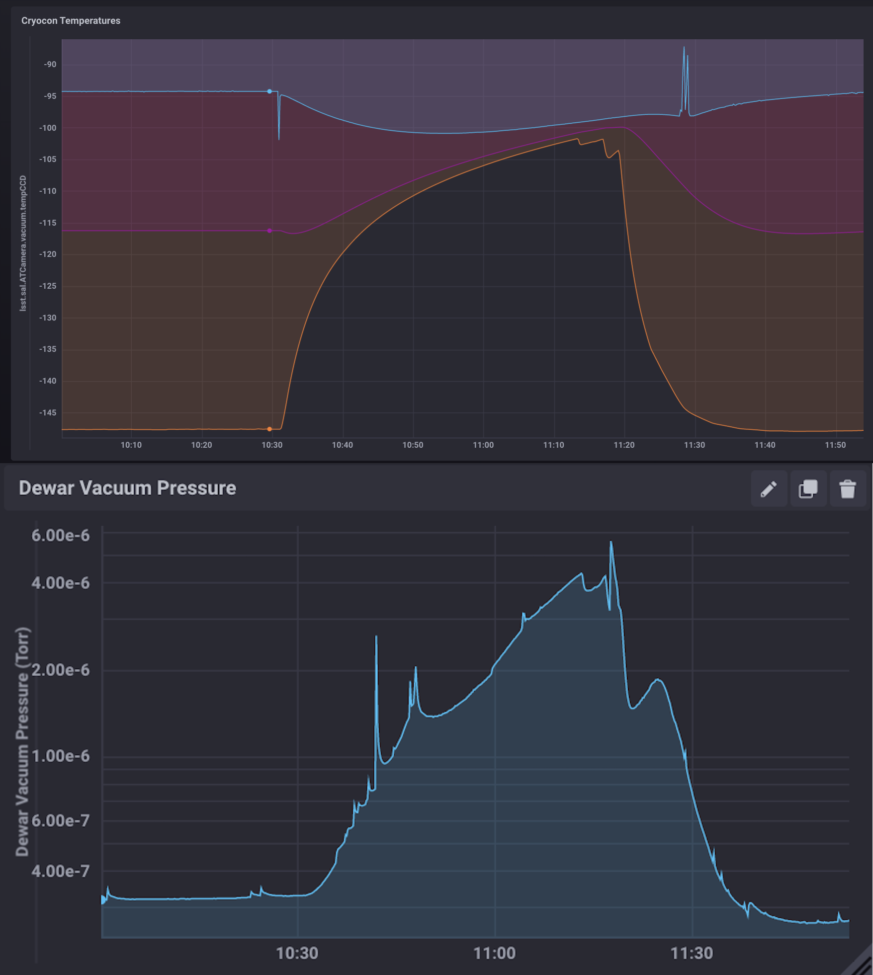
Figure 10: Temperature and pressure rise during the return line de-icing and insulation procedure on 15-Dec-22. This was accomplished without the CCD warming significantly. The turbopump was attached to the Dewar during this procedure to prevent the pressure from rising too much.
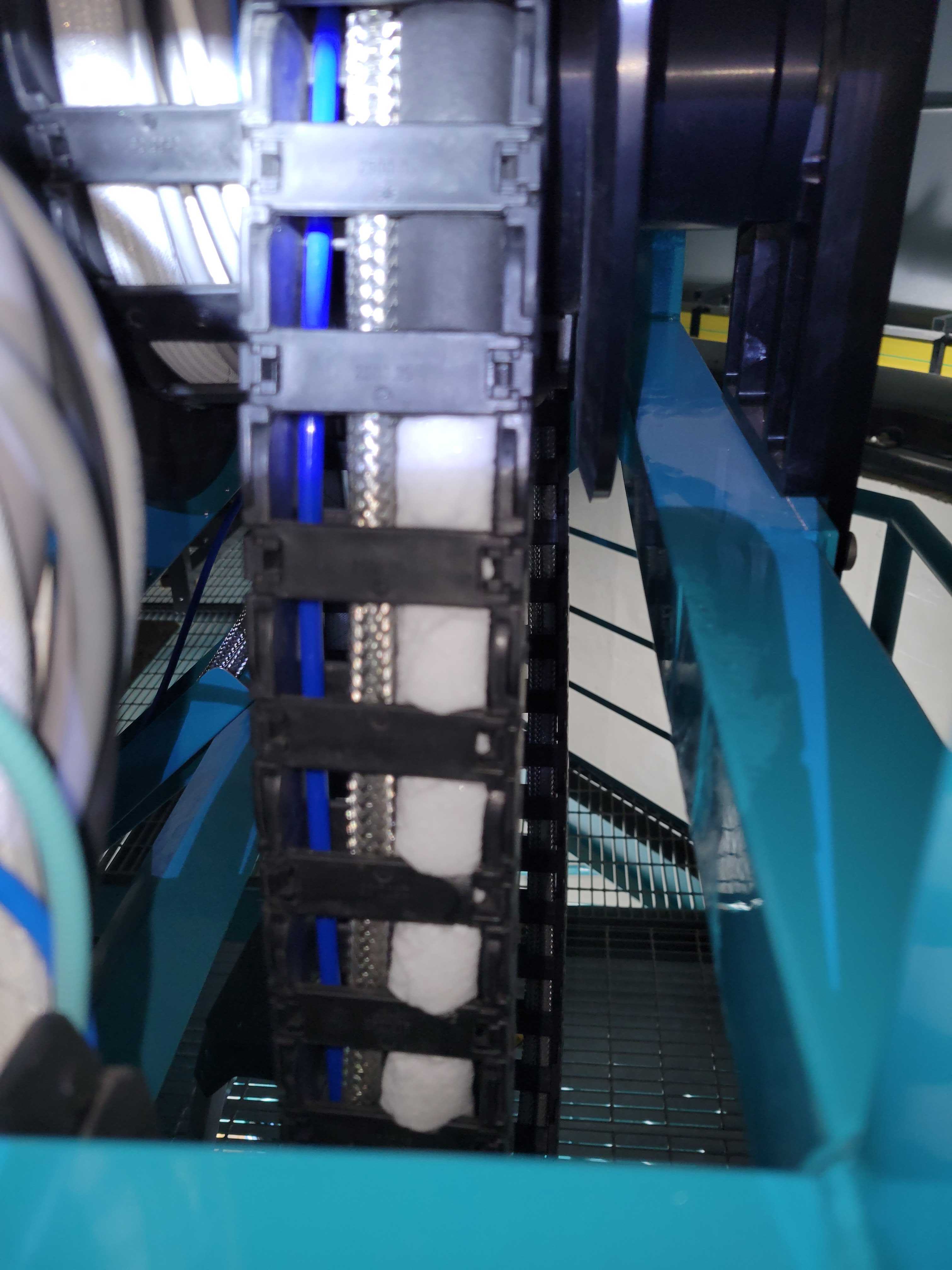
Figure 11: Line icing in the cable wrap.
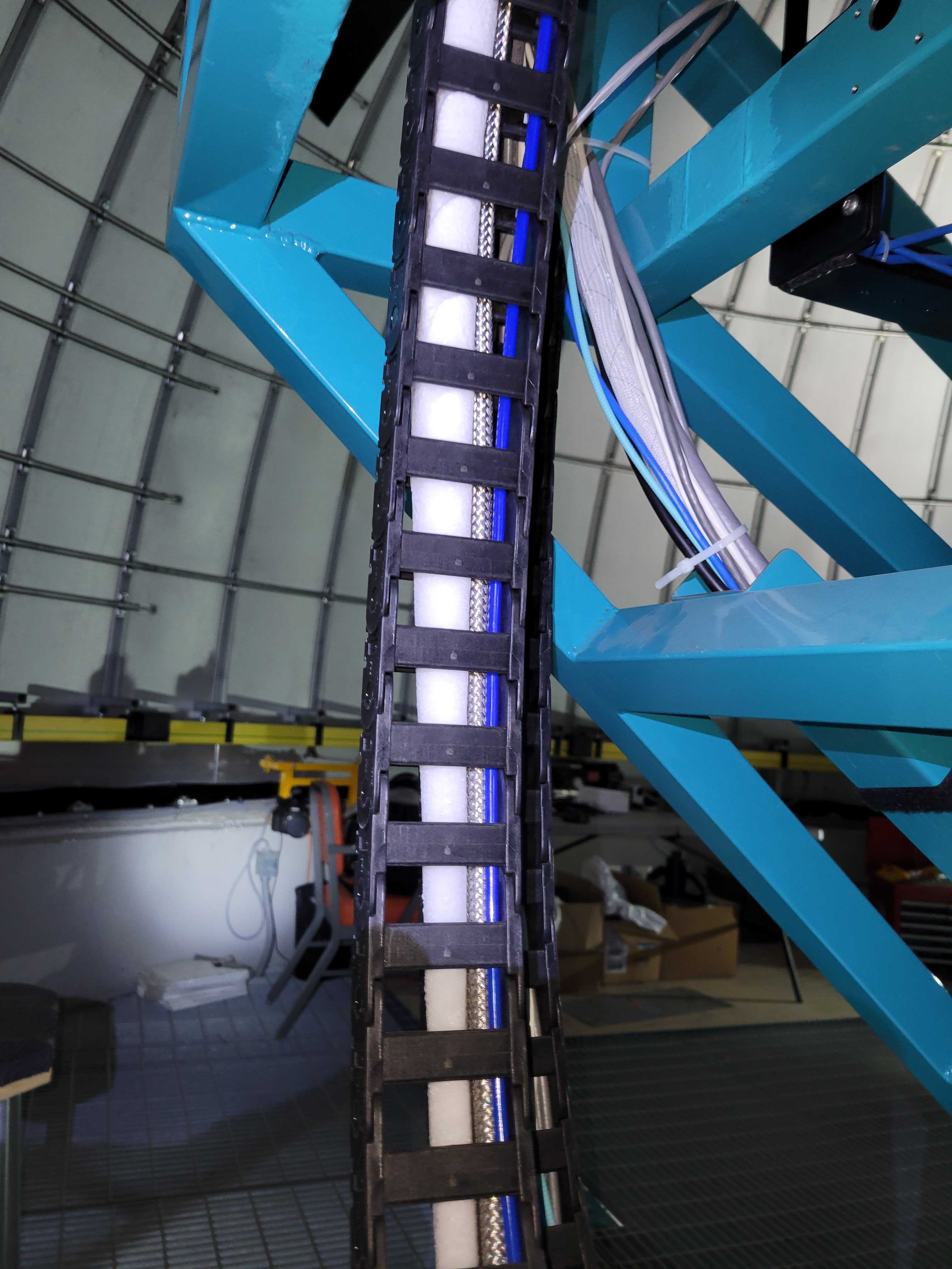
Figure 12: Line icing in the cable wrap.
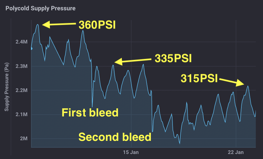
Figure 13: Gas was bled out of the system in two steps to reduce the system pressure.
Changing the internal absorber and swapping compressors.#
The Polycold chiller compressor contains an internal absorber that removes contaminants from the refrigeration fluid. Note that there is also an external absorber mounted on the wall behind the compressor. The internal absorber needs to be changed out about once per year and replaced with a new absorber.
The easiest way to perform the absorber change is as follows:
Get the spare compressor, which is stored in the AuxTel shipping container. Also in the container you should find a new internal absorber. If it is not there, it will need to be ordered.
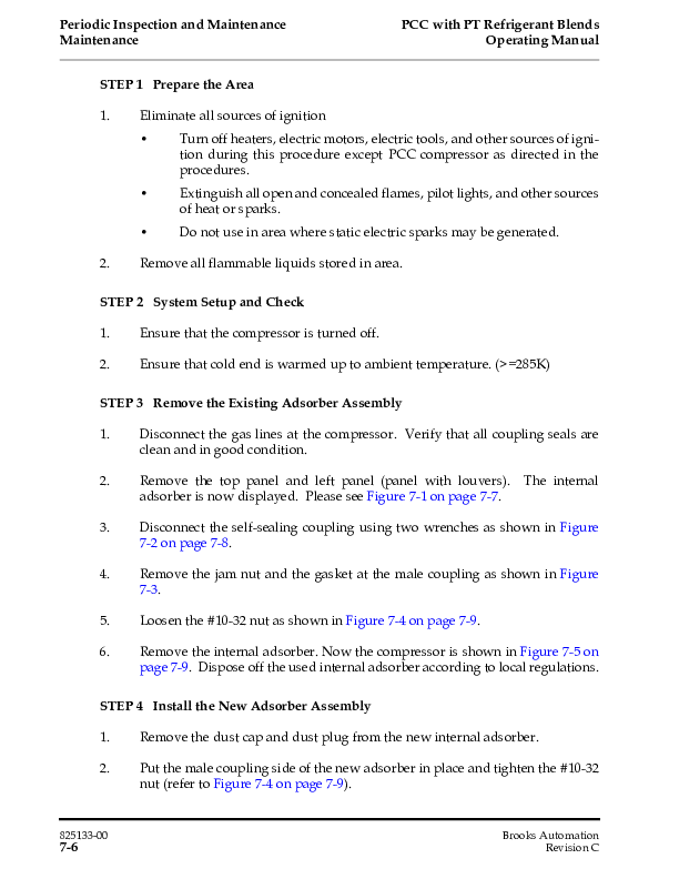
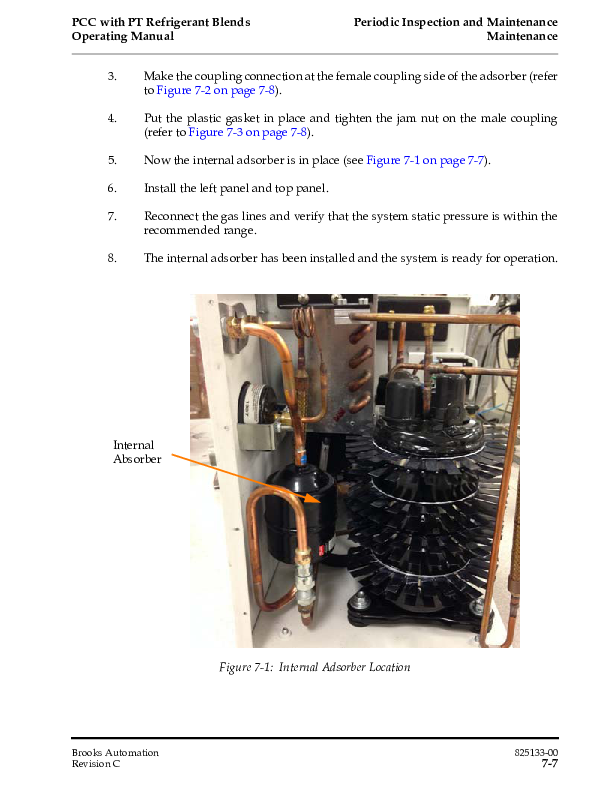
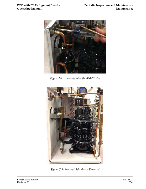
Replace the internal absorber in the spare compressor. The steps to do this are shown in detail in the Polycold manual, and those pages are copied below. The old absorber should be discarded. It should be given to the Rubin safety team so it can be discarded safely.
Turn off the compressor, move the supply and return lines to the new compressor and turn the new compressor on. This should be done as quickly as possible so that warm-up of the Dewar is minimized.
Put the old compressor (which is now the spare) back in the AuxTel container until the next swap.
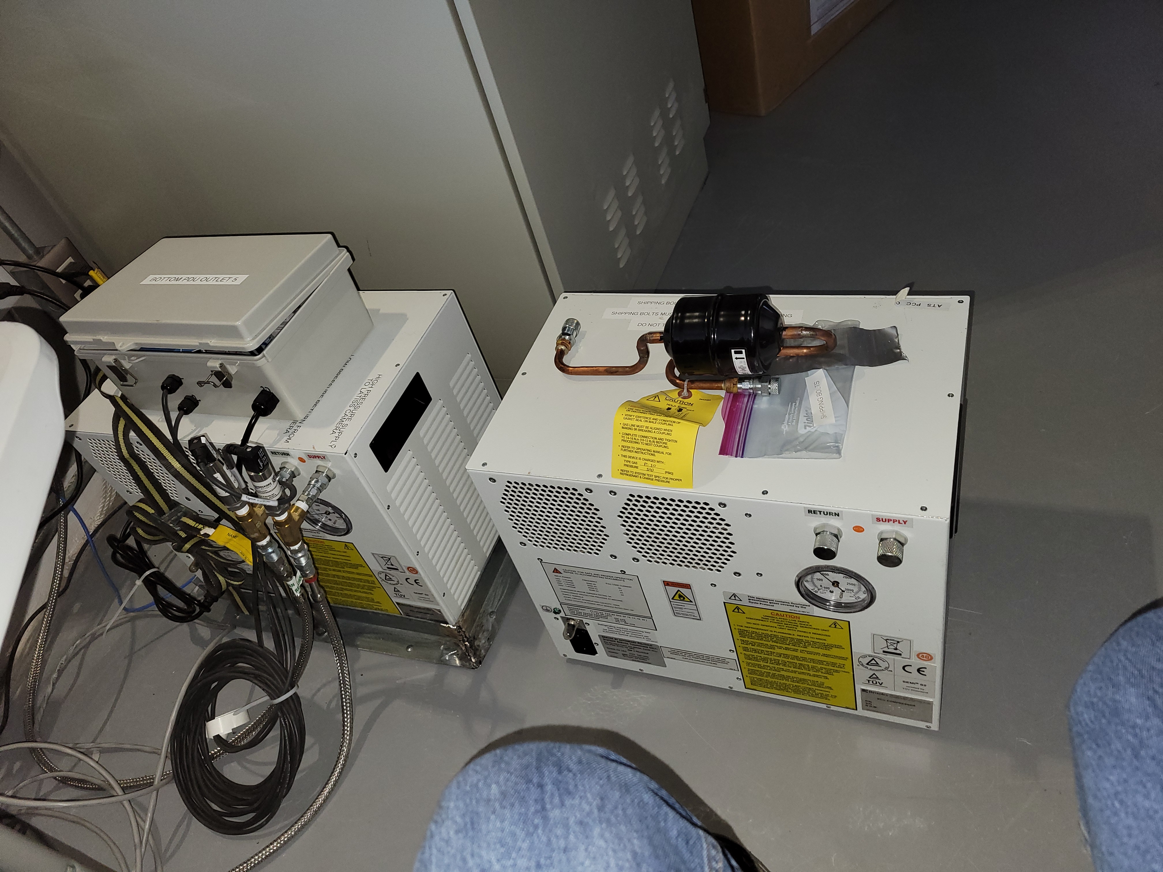
Figure 14: Preparing for chiller swap. The current compressor is on the left, the spare unit is on the right. The new internal absorber is on top of the spare unit.
Internal absorber swap details from Polycold manual (link available below):#
Changing the external absorber#
In addition to the internal absorber, there is another external one mounted on the wall, behind the Polycold compressor. As with the internal absorber, it needs to be changed out about once per year. It is assumed that the new external absorber is filled with PT-30; it should be indicated in the package. To change it, follow this procedure below:
Turn off the Polycold compressor.
The external absorber (see Figure 15) is connected on one of its ends to the supply line of the Polycold compressor. Disconnect that end with the right keys. Exercise the same precautions as outlined earlier in the procedure.
Disconnect the other end, which is inmediately above the absorber.
Once disconnected for both ends, it needs to be unmounted from the wall. While supporting the absorber with one hand, use a wrench to unfasten the nuts that secure it to the wall bracket (see Figure 15).
Secure the new absorber to the wall bracket with one hand while tightening the nuts with the other. Ensure the unit is properly mounted.
Connect both ends of the new absorber using the appropriate wrenches. Ensure all connections are secure.
Turn on the Polycold compressor.
Figure 15: External absorber, mounted on the wall behind the Polycold compressor.
Polycold manual#
The Polycold manual is available at:
https://www.apo.nmsu.edu/arc35m/Instruments/ARCTIC/Development/ImagerPDR/BrooksPCCmanual.pdf
